1 Autocad - tips
Following Autocad-tips are gathered the past 3 years. For future reference I post them here in this blog.
If I have enough time, I’ll split up all the articles in independent articles. But for now, I keep this as a giant mess.
Some are easy [*], others more advanced [**] and hardcore [***].
Good luck!
1.1 Selecting and moving items
1.1.1 6 SHIFT Key Combination You Might Not Know *
It is great to know that AutoCAD has so many productivity tools that we can use. Some of us might use it, some might not. And the rest just don’t even realize that the tools exist. Autodesk has change several command line tools, shortcut key combination several times.
Many people don’t realize that using shift combination can increase their productivity a little bit.
1. Hold [shift] + right click
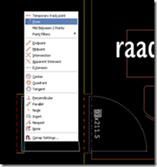
This shortcut key combination will display context menu for snap overrides. I love this one. Try to hold [shift] then right click.
2. Hold [shift] for temporary ortho mode
Holding this key while you draw, will activate temporary ortho mode. Exactly like when you activate ortho mode by pressing [f8]. But this is just temporary.
3. Hold [shift] + left click
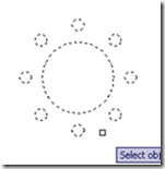
When you select many object for modification, sometimes it’s easier to select it all, then remove some objects from selection set.
4. Holding [shift] while chamfering and filleting
You know what will happen if we hold this shortcut key when we use chamfer or fillet? It will override the distance or radius value, and will use 0 (zero) value!
5. Holding [shift] while using trim/extend
When we use trim, sometimes we want to extend other objects to the same reference. You don’t have to finish your trim session, and activate extend to do it. Just hold [shift], then trim will be inverted to extend command. This work on the other way when extend command is active, it becomes trim!
6. Holding [shift] and pressing [space]
How many times have you tried to pick an object that was underneath another object? Sometimes it's not so easy, especially if you have several objects in a busy area.
Solution: Start your command (move, copy, delete, whatever). Place your cross hair over the desired object (or stack of objects).
If you can't select the proper object, press the shift key and spacebar (Shift+Spacebar) simultaneously to toggle through the stacked objects. When the object you want is highlighted, pick it and you are on your way.
1.2 Polylines*
…
1.3 Layers
1.3.1 Layer Filter Properties
1.Question:
Is there an operator to exclude xref layer names in the layer properties filter?
Answer:
~*|*
2.Question:
Is there an operator to include xref layer names in the layer properties filter?
Answer:
*|*
1.4 Hatching*
1.4.1 Associative hatches *
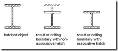
As you can see in the example above, associative hatches are extremely awesome!
Using them by default will help you draw faster and lowers the overall frustration.
More info?
http://www.upfrontezine.com/tailor/tailor12.htm
1.4.2 Edit the boundary of a non-associative hatch object *
http://ltunlimited.typepad.com/my_weblog/2009/02/edit-nonassociative-hatch-objects.html
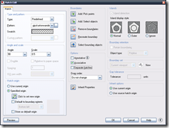
or choose ‘Recreate boundary’ in the hatch editing window to recreate the boundary.
1.4.3 Hatch spacing too dense, or dash size too small **
When you see this error, you can adjust MaxHatch. This variable controls the number of elements a hatch can create. The default value is 10000. To find out the current value, type the following commands on your command line. Be careful this command is case sensitive.
getenv
MaxHatch
To increase that number to its maximum, use the following commands.
setenv
MaxHatch
100000000
In full AutoCad you can use this command (setenv "MaxHatch" "100000000")
1.4.4 Problems with (solid) hatching?*
Close the polyline you want to hatch!
1.5 Text*
1.5.1 Convert MTEXT to TEXT**
Use EXPLODE on the MTEXT-object
1.5.2 MIRRTEXT**
When you mirror objects with MIRROR command the texts may become backwards or rather mirrored. To disable this feature alter MIRRTEXT system variable to 0. MIRRTEXT is saved in current drawing file. It accepts two values:
0: Retains text direction
1: Mirrors the text
1.6 Dimensions
DIMTEDIT: change manually dimension text
1.7 OOPS *
The OOPS command allows you to restore the LAST thing you erased and is typed in at the Command prompt.
Thanks to Peter for this easy to remember command!
1.8 Command prompt **
Has the command prompt suddenly disappeared?
Press CTRL+9 to show it again.
1.9 Blocks*
1.9.1 Edit in-place*
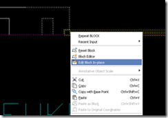
Blocks and xrefs can be edited in-place when you right click on them and choose: Edit In-place
Warning!
Also, xref’s can be edited this way! But this is a very unrecommended method of working!
1.9.2 Undefined block**
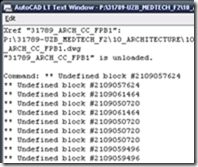
When you receive an “Undefined block”-warning, these are the steps to be taken:
1) Purge all items you can purge. *
2) Deattach all xrefs and purge again. *
3) If that doesn’t work: WBLOCK the whole drawing. **
4) If that doesn’t work: Recover the drawing.**
5) If that doesn’t work: Ask a professional for help. ***
1.9.3 Find and select blocks with a given attribute.
If you want to "FILTER" or "QSELECT" blocks containing a given text string in their attributes, you can use the standard command FIND a select them to a grip selection (and the "P" selection set).
Check the option "List results" in the Find dialog, click Find, and with the results listed, click on the "Create Selection Set" button.
1.9.4 A few adaptations to the ‘lokaalgegevens’ block ***
xxx
1.9.4.3 Block Attribute Position
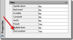
In AutoCAD 2006, as part of the dynamic block functionality, the new Lock Position property was added to block attributes. It’s enabled by default because if you define a dynamic block and want the attribute's position to be included in an action's selection set, it must be locked. An additional benefit of locking the position, especially with dynamic blocks, is that the attribute grips are not displayed when the block insertion is selected. This helps simplify the appearance of selected blocks making it easier to see the dynamic block grips without being overwhelmed by attribute grips.
The Lock Position property is turned on by default in the Attribute Definition dialog box. If you turn it off, you’ll be able to see and move block attributes within the block insertions.
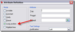
If you’ve already defined an attribute definition with Lock Position enabled, you can change it using the Properties window.
! Edit the block, then change the properties of the attributes in the properties window! Afterwards, do an Attsync!
1.9.4.4 Attsync
To update blocks that have already been inserted in the drawing, you’ll need to use ATTSYNC.
http://heidihewett.blogs.com/my_weblog/2008/05/good-question-b.html
1.9.4.5 Customize the Fields
See Customization of Fields - It is Possible! ***
1.10 Xrefs
1.10.1 Origins do not align when xref-ed ***
The base files' origins (all at 0,0,0) do not line up with the sheet file's 0,0,0.
Solution: INSBASE variable should be set at 0,0,0 in all the drawings by using the BASE command.
1.10.2 How to open a drawing without loading its Xrefs? *
1. Full AutoCad only: Use the Partial Open function to load your .DWG file (see the arrow near the Open button in the Open file dialog or the -PARTIALOPEN command). Now check only those layers that do not belong to a Xref or check the "Unload all Xrefs on open" box.
2. Full +LT: Rename the Xrefs.
1.10.3 Xref layer control and VISRETAIN**
Have you ever inserted an XREF and then spent time getting all the LAYERs turned on, off, thawed and frozen just the way you want. You then spent even more time setting each layer the color that you want. And once you had everything just perfect, you saved your drawing and exited, only to find when you return that all the time consuming work had been lost.
We’ve all done it at one time or another. And chances are, if you’ve had this problem before, you’ve said (or at least thought) a bunch of cuss words and then thought to yourself “there’s got to be a way to fix this”.
Well, you are right. And if you haven’t already figured it out, the answer lies in the System Variable VISRETAIN. VISTRETAIN controls the visibility state and colors for your XREFs. If it’s set to 1, which in most cases it should be, all the work you do to tweak the LAYERs will be saved in the drawing. If it’s set to 0, all changes will be lost and the drawing will load upon next open to the current layer conditions as found in the original XREF file.
1.11 Clean up drawings
1.11.1 Purge*
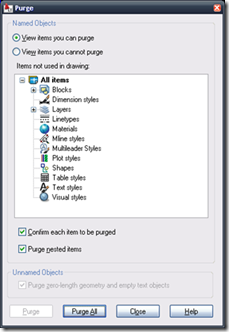
Unused named items can be removed from the current drawing by using PURGE. These include include block definitions, dimension styles, layers, linetypes, and text styles. Zero-length geometry and empty text objects can also be removed.
If you enter PURGE (or even shorter PU) at the Command prompt, options are displayed.
1.11.2 Laydel**
This command deletes all objects on a layer and purges the layer.
If you enter -laydel at the Command prompt, options are displayed.
1.12 Wipeout
1.12.1 Basic concept*
1.12.2 Frames: ON/OFF**
1.12.3 Wipeouts in a block**
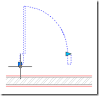
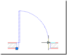
When you want to place a door as a block and add a wipeout in the background of this block, you can easily hide portions of, for example, a wall (see images below).
Image 1: Door-block containing wipeout
http://www.cadlearn.cn/html/English/2010/1214/4617.html
Thanks Luutzen! Jihaa!
!!! The wipeout will only hide all the content that is located under the wipeout. When you apply ‘Send to Back’ on this door, all the hidden content is visible again.
1.13 DesignCenter *
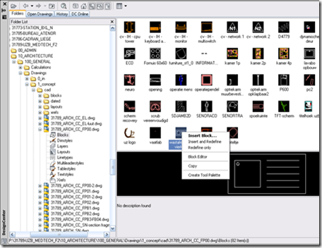
Do you quickly want to copy different items from one drawing to another? Layers, blocks, layouts, dimstyles, xrefs, … can be copied easily by using the DesignCenter.
Open the design center (via Tools à Palettes à DesignCenter or press Ctrl+2)
- Look under Open Drawings if the source file is already opened or navigate to the desired file in the folder structure.
- Choose the content you want to copy, rightclick on the items and choose Insert…
- Done!
** P.S.: as you can see in the screenshot, you can also choose Insert and Redefine. This is a more advanced option to update the content of blocks in different files. Suppose you’ve modified the contents of block XXX in one file and want to update that block in all your other drawings. By selecting the modified block XXX in DesignCenter and using Insert and Redefine, this is easily accomplished.
1.14 Autocad interface changes
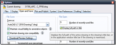
1.14.1 Display full path and file name in title bar *
Normally it’s very useful to see the full filename in the title bar. For example to avoid confusion between two drawings with the same name.
Go to ‘Options’ à ‘Open and Save’ à ‘File Open’ and choose ‘Display full path in title.
1.14.2 Enable Classiclayer **
Newer is not always better. Use the classiclayer-command to use the older but faster layermanager in AutoCAD.
*** You can add this command to the ribbon to have a quick access (via ToolsàCustomizeàInterface…) or create a custom command alias definition in the Program Parameters File for AutoCAD LT 2010 (ToolsàCustomizeàEdit Program Parameters).
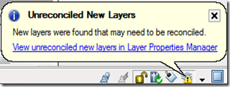
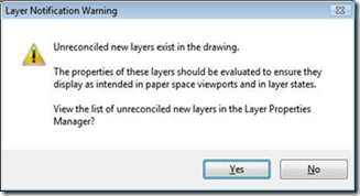
1.14.3 Disable unreconciled layers warnings ***
Do you also hate it when Autocad displays the Layer Notification Dialog every time you want to print?
Add the following items to a ‘acad.lsp’ in this location: C:\Program Files\AutoCAD LT 2010
(setvar "LAYERNOTIFY" 0)
(setvar "LAYEREVAL" 0)
(setvar "LAYEREVALCTL" 0)
And your problems are gone! J
1.14.4 Display the classic menubar **
Set the variable MENUBAR to 1.
You can also add it to the acad.lsp as (setvar "MENUBAR" 1). ***
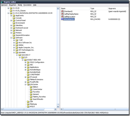
1.14.5 Disable InfoCenter ***
Disable the InfoCenter to speed up AutoCAD. You’ll never use it anyway.
You will need to open Regedit and search for InfoCenterOn. You need to change the REG_DWORD value from 1 to 0. As you can see in the screenshot below, the InfoCenter is gone now.
1.14.6 Add to Quick Access Toolbar
Just a small but useful tip this week.
For the people who use the ribbon-bar in Autocad: you can right-click on commands (icons) you want to show permanently and choose ‘Add to Quick Access Toolbar’.
Autocad makes a copy of the icon and places it in the Quick Access Toolbar.
This way, the icon stays visible, even when you switch between Tabs (Home-Insert-Annotate-…).
1.15 Viewport problems
1.15.1 Viewport automatically Zoom Extents when made active
Set UCSFOLLOW to 0 if you want to disable this annoying behavior.
http://forums.augi.com/showthread.php?t=16793
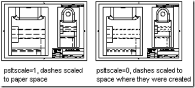
1.15.2 Linetypes not showing up correctly in viewport
In your viewport:
1) Set LTSCALE to 50 (most of the times this is the correct setting)
2) Set PSLTSCALE to 0.
1.16 Printing problems
1.16.1 xxx
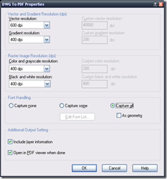
1.16.2 Dots are plotted instead of characters if you use “DWG to PDF-plotter”? ***
· Choose Properties in plot setup when ‘DWG to PDF-plotter’ is selected.
· Choose Custom Properties
· Choose Capture all to include all fonts in the plotted pdf-file.
· Press OK, OK, Save changes to the following file, OK
1.17 Advanced Autocad-scripts
1.17.1 Auto Increment Numbering Macro for AutoCAD LT
Have you ever tried automating tasks in AutoCAD LT? If so, you will find it really difficult due to lack of programming support inside it. Often this leads you to experiment with DIESEL to achieve the results you normally achieve in full version of AutoCAD. Here is a tricky macro to automate the process of increment numbering in AutoCAD LT.
*^c^c_text;\;;$M=$(+,$(getvar,USERR1),$(getvar,USERR2));setvar;USERR1;$M=$(+,$(getvar,USERR1),$(getvar,USERR2));
Configure the macro in a button (or wherever you are comfortable). Click on the button once and click on the required locations continuously to keep the incremented numbers. use USERR1 system variable to set the starting number and USERR2 for the increment. For example, suppose you need to start numbering from 1.001 and continue like 1.002,1.003,1.004........, set USERR1 to 1 and USERR2 to .001. This will enable you to do the numbering as stated before.
The above macro is restricted to work only when the text height in the current text style is 0. If you have the habit of assigning specific text height to a text style, then you should better use the following macro.
Quote:
*^c^c_text;\;$M=$(+,$(getvar,USERR1),$(getvar,USERR2));setvar;USERR1;$M=$(+,$(getvar,USERR1),$(getvar,USERR2));
I just removed only one semicolumn from the second macro after the 'Text' command. It's becuase the 'Text' command skips one step (Text height) if the current text style has already got text height assigned. Hope AutoCAD LT people find this tip very useful. Needless to say, it will give you the same result in AutoCAD full version.
*EDIT*
Thanks to a very good suggestion from Russ for adding a prefix, I ended up adding both prefix and suffix to the numbers.
*^c^c_text;\;;$M=$(getvar,USERS1)$M=$(+,$(getvar,USERR1),$(getvar,USERR2))$M=$(getvar,USERS2);setvar;USERR1;$M=$(+,$(getvar,USERR1),$(getvar,USERR2));
The macro uses USERS1 system variable to hold the prefix and USERS2 for the suffix. Thanks to comments from an anonymous visitor, I realised that USERSx system variables are not supported in AutoCAD LT. So I replaced the macro with a new one using (getenv,variable) function in place of (getvar,USERSx).
*^c^c_text;\;;$M=$(getenv,StrPrefix)$M=$(+,$(getvar,USERR1),$(getvar,USERR2))$M=$(getenv,StrSuffix);setvar;USERR1;$M=$(+,$(getvar,USERR1),$(getvar,USERR2));
You need to set two environment variables (I used StrPreifx for prefix and StrSuffix for suffix) using SETENV command which, I beleive, is available in AutoCAD LT. Don't forget to respect the text height of the current text style as mentioned eariler. Again, I don't have AutoCAD LT to test this macro. I would be really thankful if somebody could test it on LT and post a feedback on it.
1.17.2 Customization of Fields - It is Possible! ***
| Data type | Category | Format | Options | Description |
| String | Case formats | TCx | x is 1-4 | |
| 1 | Upper case | |||
| 2 | Lower case | |||
| 3 | First capital | |||
| 4 | Title case | |||
| Examples: %tc1 %tc4 | ||||
| File name formats | FNx | x is 1-7 | ||
| 1 | File path only | |||
| 2 | File name only | |||
| 3 | File path and name | |||
| 4 | File extension only | |||
| 5 | Not valid | |||
| 6 | File name and extension | |||
| 7 | File path, name, and extension | |||
| Examples: %fn1 %fn6%tc1 | ||||
| Long | Separate thousands | TH | Separates thousands using comma | |
| Byte format | BYx | x is 1-3 | ||
| 1 | Bytes | |||
| 2 | Kilobytes | |||
| 3 | Megabytes | |||
| Examples: %by1 %.2fby3 | ||||
| Boolean format | BLx | x is 1-4 | ||
| 1 | True, False | |||
| 2 | Yes, No | |||
| 3 | On, Off | |||
| 4 | Enabled, Disabled | |||
| Examples: %bl2 %bl4%tc1 | ||||
| Enum format | ENx | x is 1-6 | ||
| 1 | Text alignment: Left, Center, Right, Aligned, Middle, Fit, Top left, Top center, Top right, Middle left, Middle center, Middle right, Bottom left, Bottom center, Bottom right | |||
| 2 | MText line spacing style: At least, Exactly | |||
| 3 | Hatch object type: Hatch, Gradient | |||
| 4 | Hatch style: Normal, Outer, Ignore | |||
| 5 | Hatch pattern type: User defined, Predefined, Custom | |||
| 6 | 3d polyline type: Simple, Quadratic, Cubic | |||
| Examples: %en1 %en2%tc1 | ||||
| Double | acutPrintf formats | All the printf formats supported by acutPrintf | ||
| QFormats | QFormats supported by acutPrintf | |||
| Precision | PRx | x is precision which can be 0-8 | ||
| Format options | QFx | x is OR’d custom format flags and AcUt::QFormatBitFlags enum values | ||
| 0x1 | Don’t convert inches to foot for Arch and Eng units. | |||
| n | OR’d AcUt::QFormatBitFlags | |||
| Linear units | LUx | x is 1-6 | ||
| 1 | Scientific | |||
| 2 | Decimal | |||
| 3 | Engineering | |||
| 4 | Architectural | |||
| 5 | Fractional | |||
| 6 | Use current database units (LUNITS sysvar) | |||
| Angular units | AUx | x is 0-5 | ||
| 0 | Decimal degrees | |||
| 1 | degrees/minutes/seconds | |||
| 2 | Grads | |||
| 3 | Radians | |||
| 4 | surveyor's units | |||
| 5 | Use current database units (AUNITS sysvar) | |||
| Conversion | CTx | x is 1-4 | ||
| 1 | Inverse the value (1/x) | |||
| 2 | Foot to inch (x*12) | |||
| 3 | Inch to foot (x/12) | |||
| 4 | Square inch to square foot (x/12*12) | |||
| Examples: %lu1%pr2 %au2%pr3 %lu1%qf3072 %lu1%pr2%qf3072 %lu4%pr8%ct2%qf2816 |
Toevoegen op lijn 1025 in
C:\Users\xxx\AppData\Roaming\Autodesk\AutoCAD LT 2012 - English\R17\enu\Support\AcFields.fdc (make backup first)
<Format>
<DisplayName>Square meters (VK)</DisplayName>
<FormatString>%lu2%pr2%ps[, m²]%ct8[1e-006]</FormatString>
</Format>
1.18 Autocad performance
This has reportedly made a big difference when running ANY version of AutoCAD on a Win7 64 machine.
Go to:
Control Panel
All Control Panel Items
Network and Sharing Center
Change Adapter Settings
Right-Click "Local Area Connection"
Select "Properties"
Click "Configure"
Select the "Advanced" tab
Select the "Speed & Duplex" Property and set the value to "Auto Negotiation"
If it's already set that way, change it to the highest network speed your network is capable of and see if that fixes your issue. If it does, but the problem reccurs after a reboot, then change it back to "Auto Negotiation".
1.19 Autocad performance
How to recover your cad stuff:
1- In A’cad type: OP > enter
2- Go to tab: Files
3- Copy the link stored in the: Automatic save location
4- Paste this link in your explorer
5- Order the directory on: Type
6- Search for the files with the .sv$ or .bak extension
7- Select the one you think is the most up to date
8- Change the .sv$ or .bak extension to .dwg
9- Open the file and shave ass in the location you want
10- Et voila







Geen opmerkingen:
Een reactie posten